Get in touch! +91 79 6952 7575 / [email protected]
RNewsletters
Pressure regulating hydrant valve
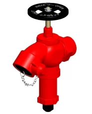
Pressure Regulating Hydrant valves regulate the outlet pressure to a safe limit, where inlet pressures can be higher than the normal working pressure. They are normally mounted onto wet risers or on stand posts fitted on the fire water network.
Brief Description: AAAG Pressure Regulating Hydrant Valve, Oblique type, High Pressure, made of Stainless Steel, having 3” Flanged inlet, and 2½” (63 mm) female instantaneous outlet, provided with handwheel for operation, complete with blank cap and chain.

Download
AAAG-PRESSURE-REGULATING-HYDRANT-VALVE-SS304.pdf| 1 | GENERAL DATA | |
| 1.1 | Make | AAAG |
| 1.2 | Size | 3” (80 mm) – Flanged |
| 1.3 | Inlet | 3” Flanged inlet (Drilling as per ANSI B16.5 150# FF) |
| 1.4 | Outlet | 2½” (63 mm) Female Inst. Adaptor |
| 1.5 | Reference Standard | NIL |
| 2 | MATERIAL OF CONSTRUCTION | |
| 2.1 | Body, Bonnet, Female outlet and parts | S.S. 304 (IS: 3444 Gr. I) |
| 2.2 | Stem | IS: 6603 (SS 304) |
| 2.3 | Pressure Regulating Mechanism | SS 304 (IS: 3444 Gr. I) |
| 2.4 | Hand Wheel | Cast Iron (IS: 210) |
| 2.5 | Washers | Natural Rubber as per IS: 937 |
| 3 | TESTING AND QUALITY CONTROL | |
| 3.1 | Dimensional check | Dimensions as per Drawing (See below) |
| 3.2 | Seat Leakage Test | 14 bar for 2 minutes |
| 3.3 | Valve Body Test | 21 bar for 2 minutes |
| 3.4 | Pressure Regulation Test | Outlet pressure of 4.5 +/- 0.5 bar at varying inlet pressures (12.5, 17.5, 20.5 bar) with flow of 510 +/- 30 lpm |
| 3.5 | Documentation | Internal inspection report, supplier’s certificates, approved laboratory test certificates |
| 4 | OPERATIONAL/ TECHNICAL DATA | |
| 4.1 | Working pressure range | upto 16 bar |
| 4.2 | Weight (approx.) | NIL |
| 5 | FINISH | |
| 5.1 | Body | Painted - Fire Red Color |
| 5.2 | Wheel | Painted - Black Paint |
| 5.3 | Parts | Polished |
| 6 | APPROVALS & MARKING | |
| 6.1 | Approvals | NIL |
| 6.2 | Marking on Hydrant valve | AAAG/ Size/ Year of Manufacture/ SI No |
| 7 | WARRANTY | |
| 7.1 | Warranty & Guarantee | 12 Months from the date of supply |
